Start OpenSCAD
There are several basic shapes, or 'primitives', in OpenSCAD that you can use as building blocks.
Primitives
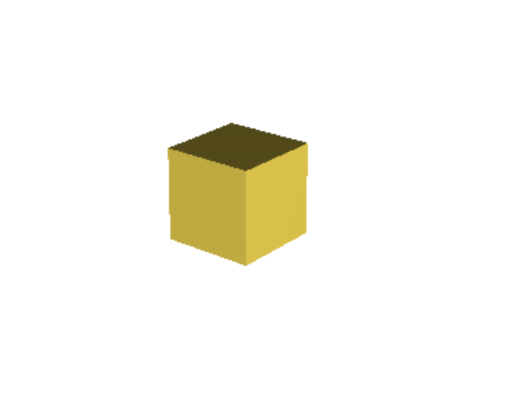
The Cube
You can also specify different lengths for each side:

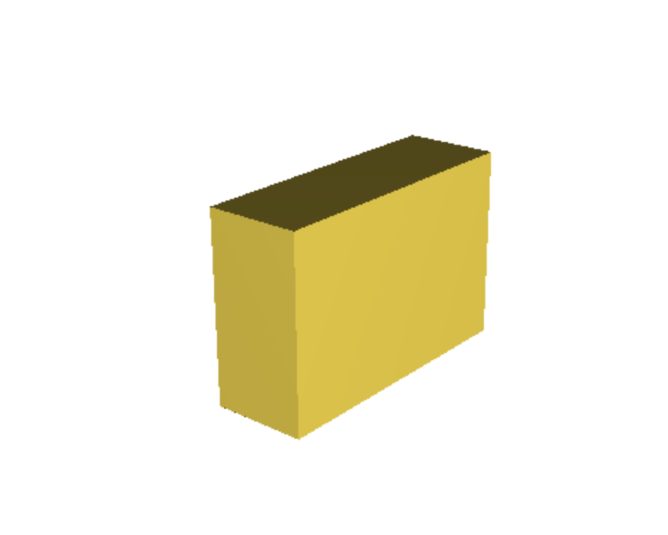
To create a cube with a side length of 10mm:
cube(10); cube([10, 20, 30]); The Sphere
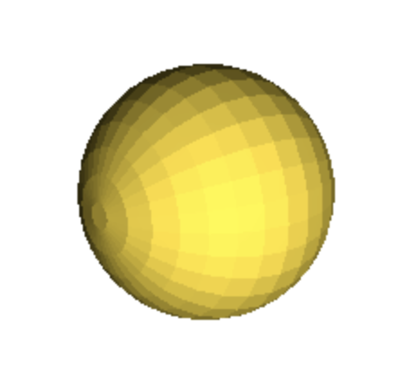
Adding the $fn parameter allows you to control the facet-number or how rough the surface is.
To create a sphere with a radius of 10mm:

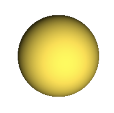
More facets require longer loading times but produce smoother surfaces
sphere(10);sphere(10, $fn=1000)The Cylinder
Adding the $fn parameter allows you to control the facet-number or how rough the surface is.
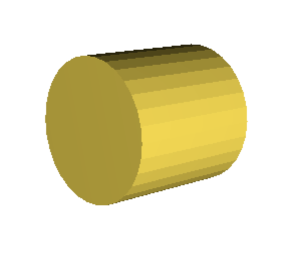
To create a cylinder with a height of 20mm and a radius of 10mm:
More facets require longer loading times but produce smoother surfaces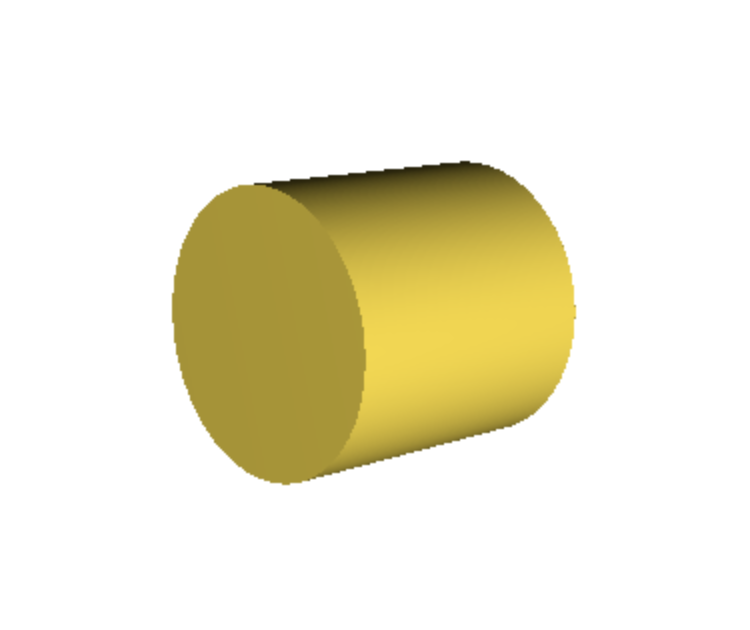

cylinder(h = 20, r = 10);cylinder(h = 20, r = 10, $fn=500);There are several operations that let you combine and modify these primitives to create complex ideas.
Operations
Translate
Transform operations like translate, rotate and scale let you change the position, orientation and size of your objects. For example, to create two cubes and move one 20mm along the X axis:
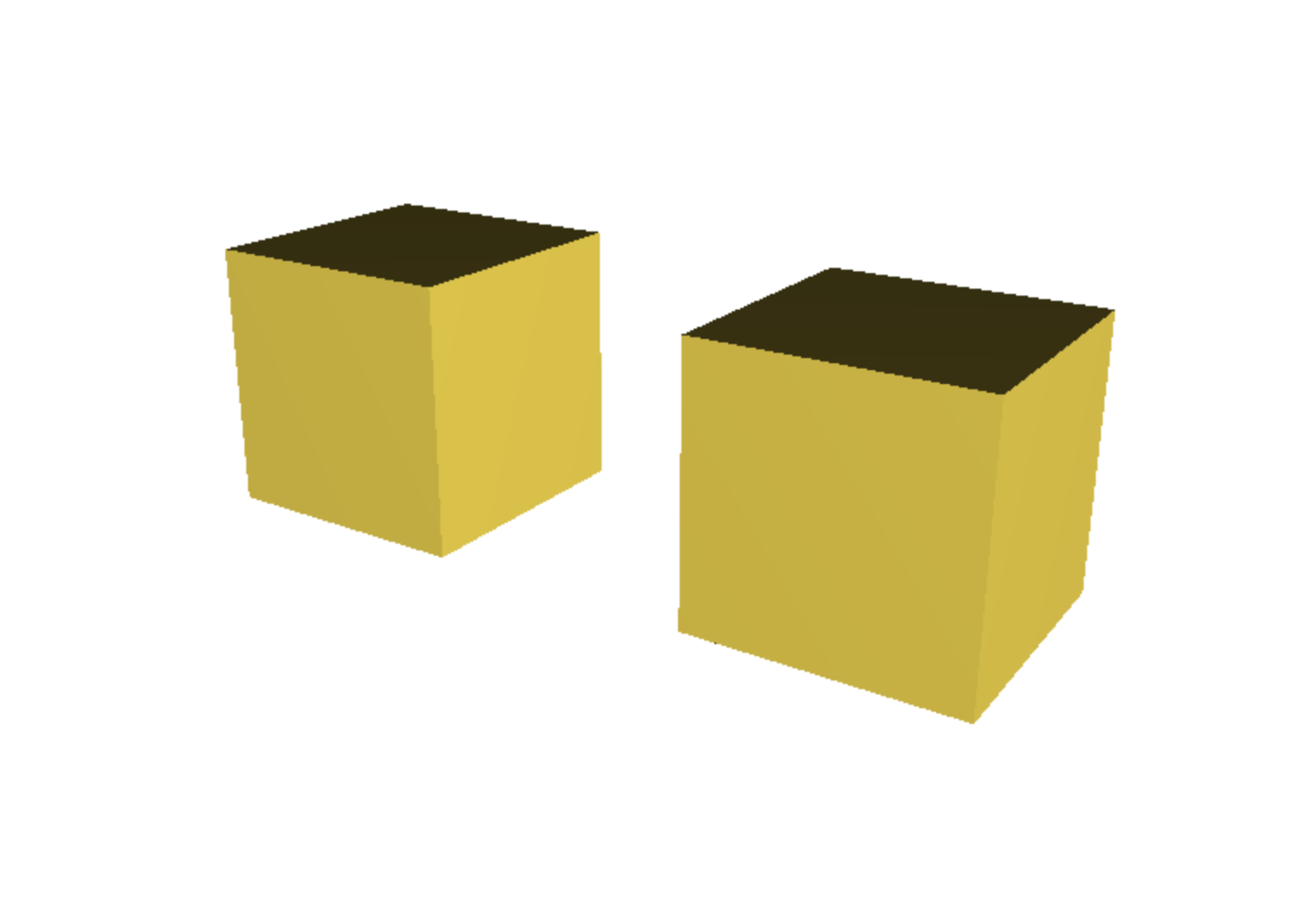
cube(10);
translate([20, 0, 0])cube(10);
Difference
Difference subtracts the second (and any subsequent) object(s) from the first:
difference() {
	cylinder(h = 40, r=10, center = true);
	rotate([90,0,0])cylinder(h = 20, r=5, center = true);
}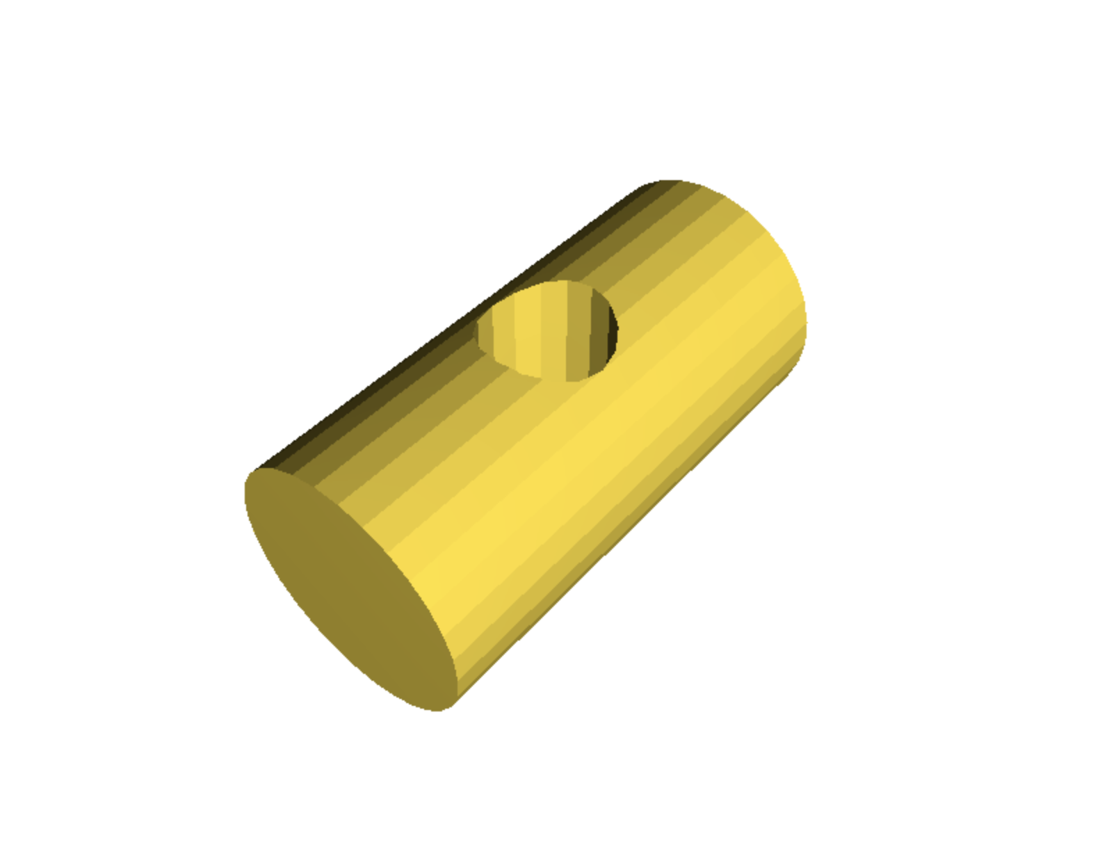
The use of the 'center = true' parameter places the objects very center at the the origin point [ X = 0, Y = 0, Z = 0]Difference
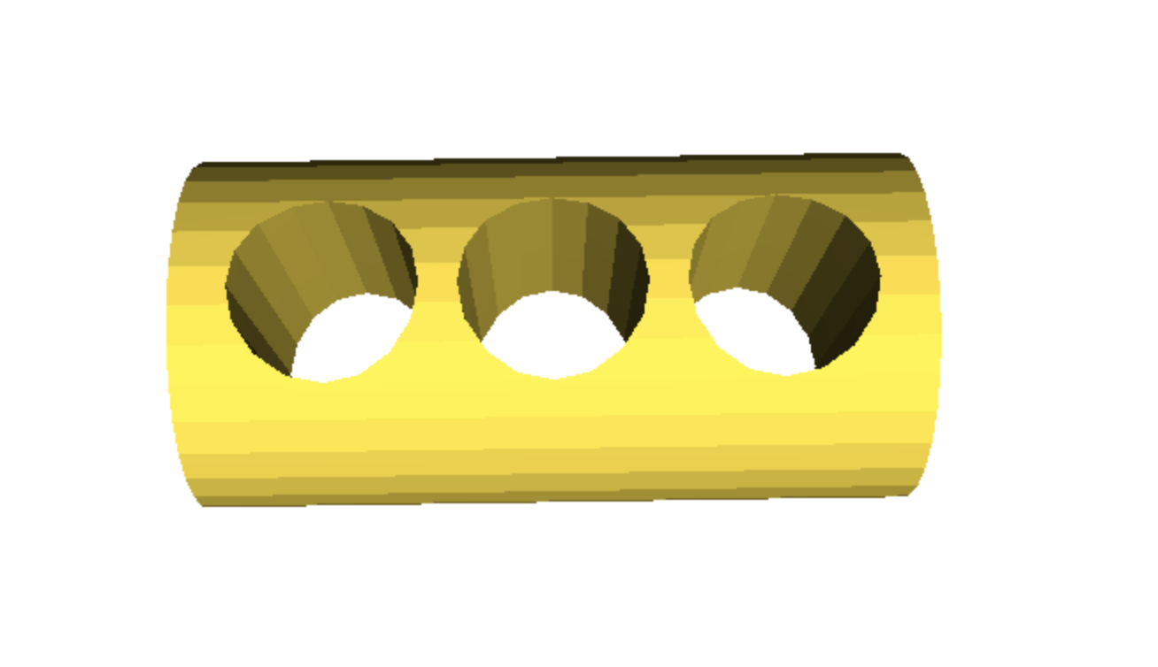
By creating two more cylinders and translate them 12mm +/- in the Y axis, we can begin designing a more complex object:
difference() {
	cylinder(h = 40, r=10, center = true);
	rotate([90,0,0])cylinder(h = 20, r=5, center = true);
	rotate([90,0,0])translate([0,12,0])cylinder(h = 20, r=5, center = true);
	rotate([90,0,0])translate([0,-12,0])cylinder(h = 20, r=5, center = true);
}
Intersection
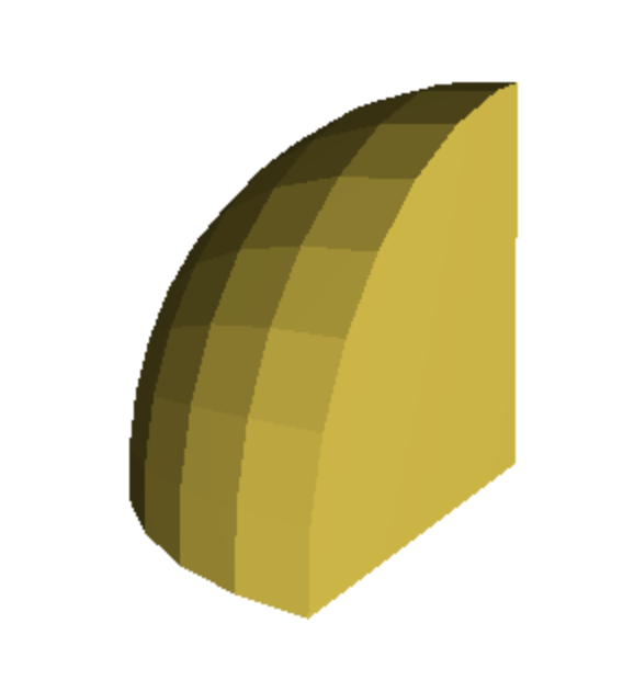
Intersection leaves only the parts where the objects overlap:
intersection() {
  cube(10);
  sphere(10);
}
Now we are going to create a 3D model of an Xbox controller thumb grip by combining the methods, primitive and functions we just learned.
3D Modeling - Xbox Controller Thumb Grip
Thumb Grip Base
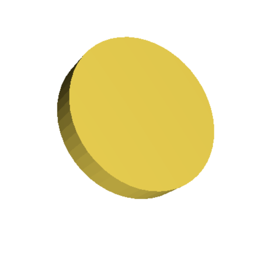
First, we create the base of the thumb grip, which is a simple cylinder. The $fn=50 parameter sets the number of fragments for a full circle. This makes the edges of the cylinder smoother.
cylinder(h = 3, r = 8, $fn=50);
Thumb Grip Top
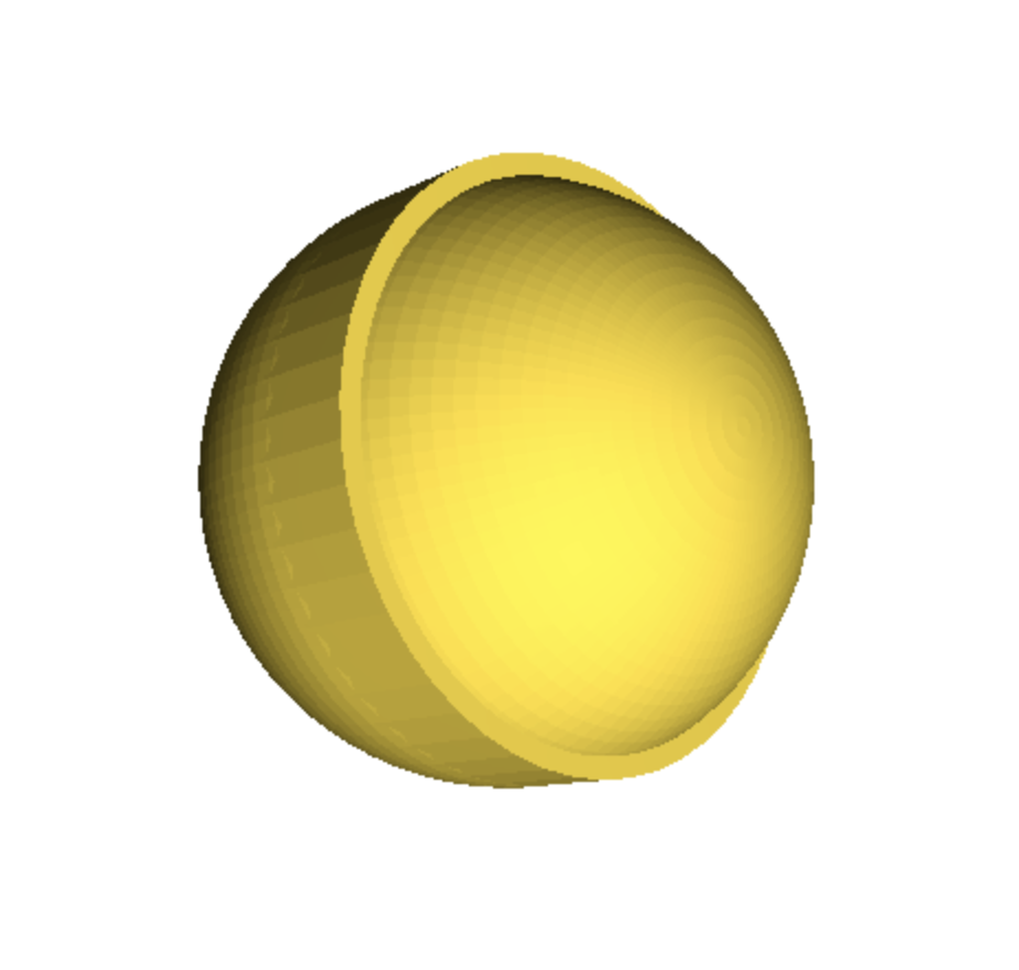
Next, we create the top of the thumb grip, which is a sphere. The sphere is moved up by 3mm along the z-axis to sit atop the base cylinder.
cylinder(h = 3, r = 8, $fn=50);

translate([0, 0, 3])
sphere(8, $fn=100);
Thumb Grip Ridges
Now, we add ridges to the thumb grip by subtracting smaller cylinders from the sphere. Note that we have adjusted the translation and the height of the cylinder to ensure that it cuts through the sphere.
In this step let's visualize everything before subtracting with the difference function.
cylinder(h = 3, r = 8, $fn=50);

translate([0, 0, 3])
sphere(8, $fn=100);

for (angle = [0:45:360]) {
  rotate([0,0,angle])
  translate([0, 6, -5])
  cylinder(h = 16, r = 1.5, $fn=50);
}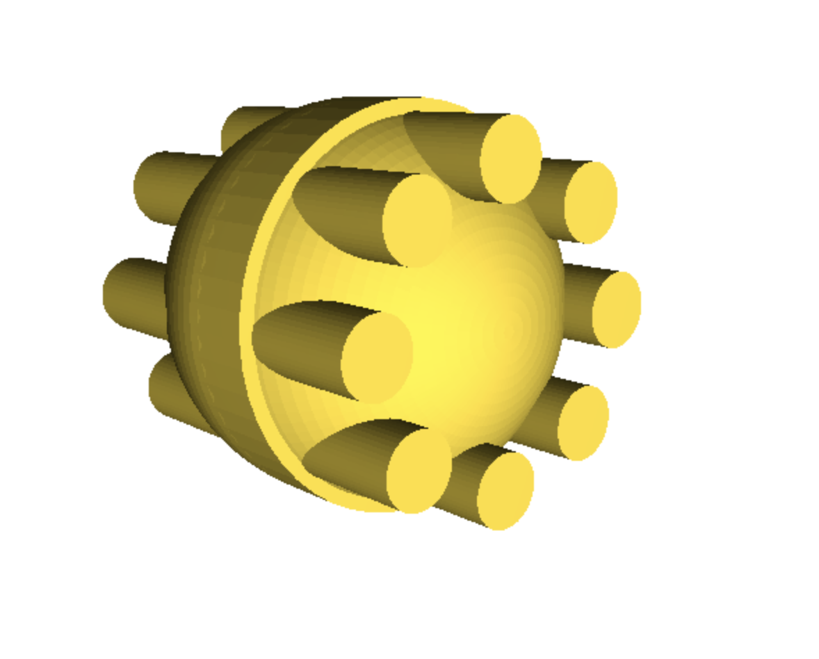
The for statement is used to repetitively subtract smaller cylinders from the sphere to create ridges on the thumb grip. The loop iterates over a range of angles from 0 to 360 in steps of 45 degrees, rotating and placing each small cylinder around the sphere, creating a uniformly ridged pattern.Thumb Grip Ridges
Before subtracting with the difference function, lets be sure to add a cylinder to flatten out the bottom of our thumb grip:
cylinder(h = 3, r = 8, $fn=50);

translate([0, 0, 3])
sphere(8, $fn=100);

for (angle = [0:45:360]) {
  rotate([0,0,angle])
  translate([0, 6, -5])
  cylinder(h = 16, r = 1.5, $fn=50);
}

cylinder(h = 12, r = 8, $fn=50);
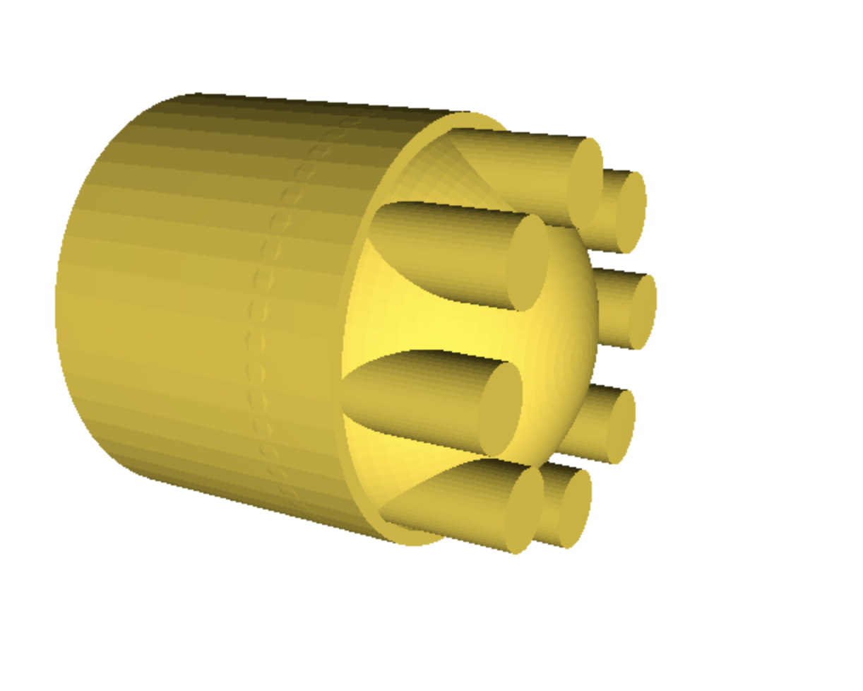
Complete Thumb Grip
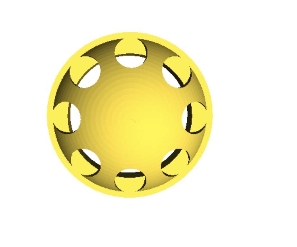
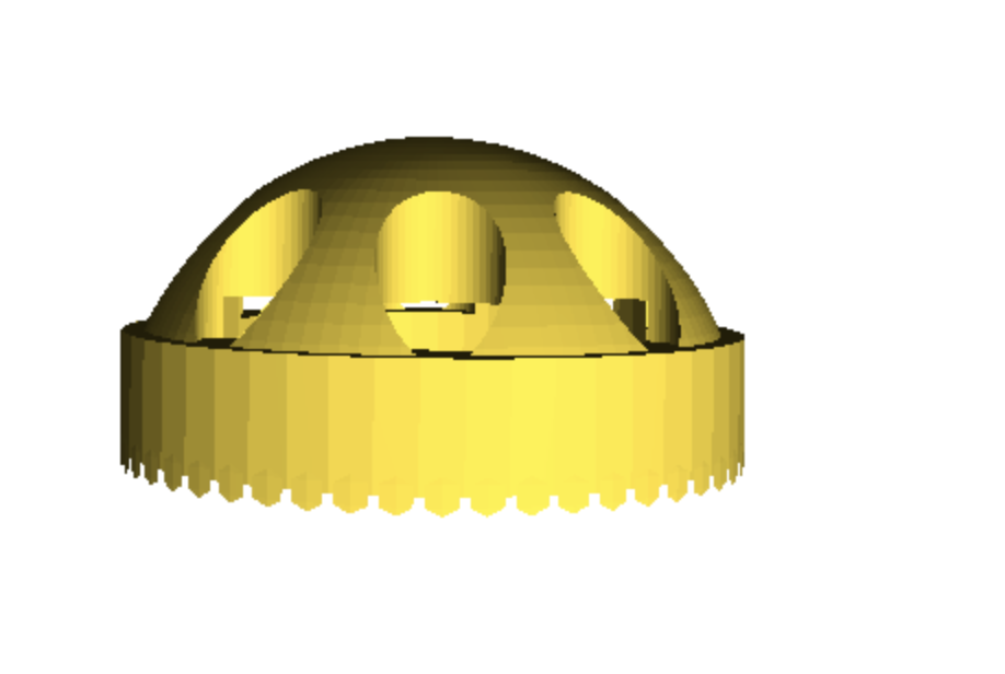
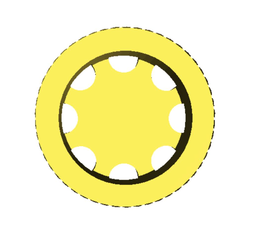
Finally, we use the difference() operation to subtract all the ridges and inner cylinder from the sphere, and the union() operation to combine the base and top into a single thumb grip. This forms the main body of the thumb grip.
difference() {
  union() {
    cylinder(h = 3, r = 8, $fn=50);
    translate([0, 0, 3])
    difference() {
      sphere(8, $fn=100);
      for (angle = [0:45:360]) {
        rotate([0,0,angle])
        translate([0, 6, -10])
        cylinder(h = 40, r = 1.5, $fn=50);
      }
      cylinder(h = 10, r = 8, $fn=50);
    }
  }
}
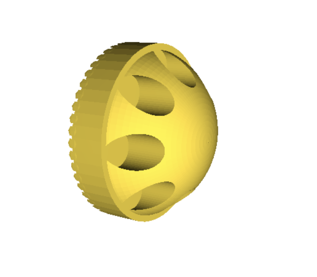
Adding the Connector
We need to create a connector to attach the thumb grip to the controller. We do this by creating a cylinder below the main body of the thumb grip.
difference()
{
  union() {
    cylinder(h = 3, r = 8, $fn=50);
    translate([0, 0, 3])
    difference() {
      sphere(8, $fn=100);
      for (angle = [0:45:360]) {
        rotate([0,0,angle])
        translate([0, 6, -10])
        cylinder(h = 40, r = 1.5, $fn=50);
      }
      cylinder(h = 10, r = 8, $fn=50);
    }
  }
  translate([0, 0, -1])
  cylinder(h = 5, r = 6, $fn=50);
}
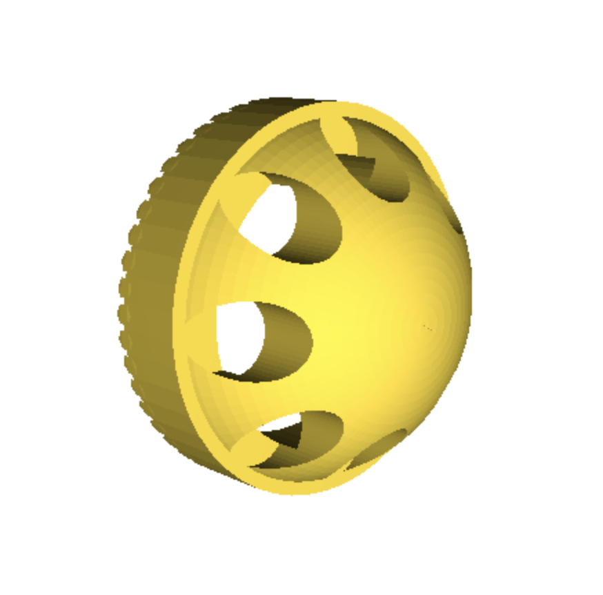
Your Thumb Grip is Ready to Print!
Congratulations on creating a complex 3D model in OpenSCAD! The journey doesn't end here. Experiment with different shapes, sizes, and operations to see what else you can create.
Remember, the key to success OpenSCAD is understanding the importance of structure, detail, syntax, and logical thinking. Happy modeling!
